Making radio detectors - Skip to the showpiece!
Overview
This project is very different from anything I have really done before or posted about, so take this post as somewhat of an experiment showing the sort of things I get up to in my spare time. There's also a lot of complex hardware-related fields covered in this project, and quite a lot of background information needed to fully understand what is going on.
To begin with I will explain how this project came to be and what inspired it. During a session of doomscrolling social media I stumbled across an Instagram reel showcasing a system by the name of Target Blu Eye 2. This system can be installed into a vehicle and will alert a driver to the presence of emergency vehicles nearby to them, to increase their awareness whilst on the road. As someone with some previous experience working with radio technologies, I was immediately enthralled with how this product worked and how I could get one.
However, when I researched into how this worked I found that this is the only product on the market offering this kind of solution and there is almost no information on how it functions or works. Furthermore the price was prohibitively expensive and well out of the range of what I'd spend on a piece of hardware simply because I found it interesting. So naturally, I decided to try and work out how to make my own even with almost no experience with radio technologies, PCB design, or reverse engineering hardware.
Spoiler, it actually worked!
Research
The first step was working out what this device is actually doing to work out the proximity of EMS vehicles. Their store website states that it is based on "TETRA Technology" and that it is unable to "Decode, manipulate, or interfere with the radio messages broadcasted by the Airwave Network". It is also worth noting that this clarification is what makes this device legal to own and use as it in no way interprets or attempts to interpret EMS radio transmissions.
So, just how is this thing detecting EMS vehicles? Well after doing some research into the TETRA radio protocol I found out that most of these TETRA radios are in a mode which sends a form of keepalive message 17 times a second to their base station. Now if you combine this fact with the knowledge that radio transmissions follow the inverse square law, it means that almost all EMS radios are constantly transmitting signals which get louder the closer you are to them. In other words they all pretty much have a giant spotlight on top of them which gets brighter the closer you are to it.
Python detectors
So, with this theory, I did some further research. It is at this point that I discovered another company called Python Detectors that do functionally the exact same thing as these Blue Eye systems and were founded much earlier. Sadly this website no longer exists however some media of this product does. I managed to locate a video of someone replacing the battery that had failed in theirs and in that video I was able to for a moment see a full view of the device's PCB. I have limited knowledge of PCB design however I knew that this was a goldmine so I immediately began attempting to decipher its functionality.
I managed to take a frame from this video and using my existing knowledge work out what the PCB was actually doing, and happily it's pretty much exactly as I was expecting. The signal comes in through a short monopole antenna, likely specced to quarter wave. It's also likely not great as all these companies sell or sold larger external antennas. Following this it goes into a passive RF SAW filter. These take in all the RF signals being collected by the antenna, and cut out everything which isn't in their frequency range. In this case I identified it as an older now discontinued "B39391B3815Z810" filter from Qualcomm.
This filter isolates the signals between around 380 and 400 MHz, conveniently the exact range which TETRA radio operates on. This then runs into a small amplifier, likely some form of LNA, and then back into another identical filter, and another identical amplifier. This dual filter is fairly common in RF and is likely a result of the filter's maximum insertion loss of around 3.5 dB. It's worth noting that these signals are logarithmic and similar to sound; 1 dB represents a doubling in volume. That 3.5 dB loss is actually rather large.
Finally it progresses out of this filter loop into a component which I identified as the "LT5537" Log Detector from Linear Technology. This is a simple piece of hardware which outputs a variable voltage based on the dB of the radio signal inputted into it on a somewhat linear scale. For example, a voltage of 1 may be a really close/loud signal (remember the inverse square law) whilst a voltage of 0.1 may be a really far away/quiet signal.
So, what does all this mean? Well it means that all of my theories were entirely correct, and these TETRA detectors are actually incredibly simple pieces of hardware that can probably be produced for well under £100, substantially below what the current market price of everything sold by Blu Eye is.
Development, revision one
The PCB
It's now time to put all of this research and information to use.
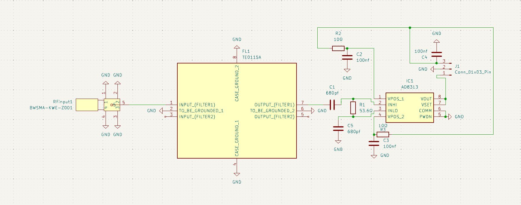
I began by choosing some more modern hardware to use for my detector, this was going to have to be on a custom PCB due to most of the components being surface mounted. I ended up using an AD8313 log meter instead of the Python Detectors LT5537. This is due to the better performance and larger availability of the AD8313. I did have some issues finding a suitable filter but I managed to stumble onto the TE0115a from TST. This is a nearly identical filter in performance to the one used on the Python Detector except with better insertion loss characteristics and it is still being produced.
Once these pieces of hardware were decided on it was a simple process of laying everything out in a schematic and designing the supporting circuitry needed as is laid out by the various components documentation. It's worth noting this is only the second PCB I have ever attempted to make, and my previous was a complete failure, so please take my schematics and designs with a pinch of salt.
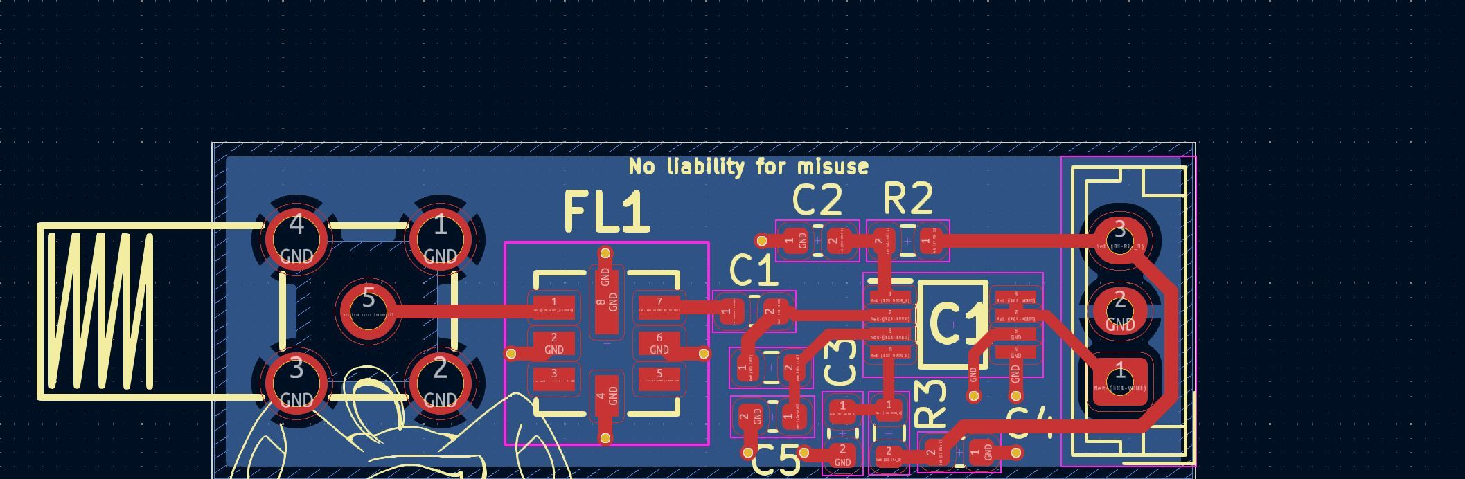
Once this schematic was designed I then laid everything out on a PCB and ended up with this, the first revision of my radio detector. There was some more work in the middle of this process involving redesigning some things to make them more RF compliant, switching to larger SMD components to make potential reworks easier, and some other things. But this is pretty much it. Following this design I ordered five of them to be produced and shipped to me for testing.
The microcontroller
The next issue I had to solve was interpreting the voltage outputted by my board. I decided upon using ESP12 boards as my microcontroller as their web interface would allow me to easily view the data captured on my phone whilst being a passenger so that I can modify things in real time. This is definitely not ideal as the ESP12's onboard radio will produce interference along with it being quite slow and generally poor at precisely reading an ADC signal.
I made some simple code which displayed a web interface and plotted a graph of the data outputted. This would be good enough for testing initially.
The antenna
The antenna has been an issue throughout this entire project and honestly, is still an issue now. I originally intended to make my own dipole antenna using two lengths of wire. As it turns out this is fine for some frequencies and works great for things like CB radio. However, it is EXTREMELY difficult to get to function properly in a car. During initial testing I went through at least ten entirely different antenna designs and layouts, all with varying degrees of terrible performance. This was until I decided to cut down an external monopole radio antenna I already had and use this for receiving. This allowed me to for the first time actually pick up an EMS vehicle driving past and was what returned hope to this project after several months of testing and failure. This antenna is not ideal as it is inconvenient to mount and generally large and annoying, however for now it is the only option as I was unable to produce my own from scratch and I do not have the excess money to spend on buying a better one.
Development, revision two
Improvements and iteration
Ok so, I now have a custom PCB capable of detecting these EMS signals, an antenna capable of picking them up, and a microcontroller which is just barely capable of actually interpreting them. This is everything I need to theoretically make a full system and with some mild changes is what resulted in the system I have now.
The first thing to go was the microcontroller. The ESP12 was never at all suitable for this project, it was just what I happened to have at hand. I switched to an STM32 “Bluepill” board. This board is substantially faster and produces much better ADC measurement results in comparison along with it not having a radio which could cause interference.
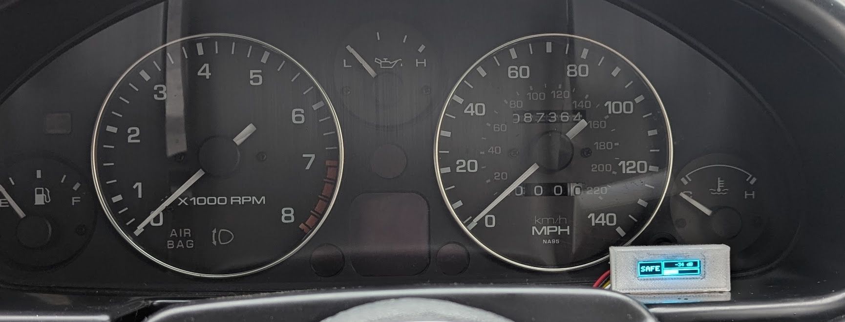
Next up the display method, obviously I am not going to make a system which requires using a phone while driving as that would be ridiculous. So, I settled on using a small 128×32 OLED display and making a simple minimal UI that won't be distracting while driving. This is an extremely subtle way of displaying the information and is ideal for this use case.
Finally I designed and 3D printed cases for both the combined unit (now with a buck converter to turn 12 V to 5 V) and the display. And after all this, I finally have the finished product after around three solid months of R&D on a subject I am entirely inexperienced in, using a series of technologies I had never heard of until I started this project, and all because the Instagram reel seemed pretty cool and I wanted to see if I could make my own!
The final product
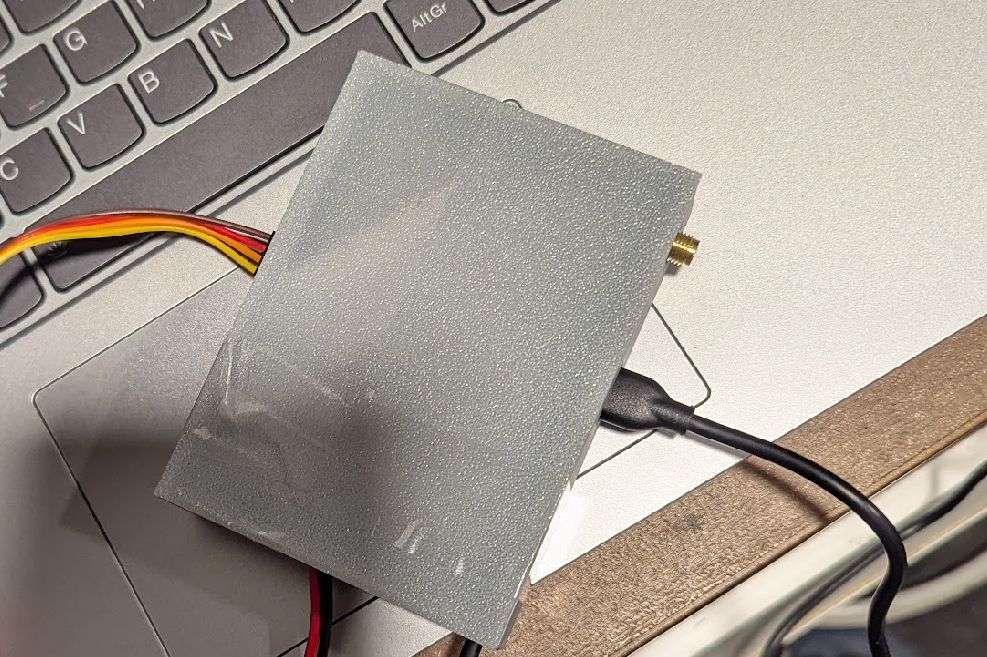
So here it is, my very own EMS detector which as far as I can tell functions the same as the commercially available options while costing me less than a tenth the price! It's nicely packaged in a 3D printed case and is surprisingly easy to install into a vehicle. It does still require an external antenna as can be seen here but that's the only thing visible externally. The display can be mounted in a variety of locations but I personally have mine mounted next to my vehicle's gauge cluster.
So does it work? As far as I can tell yes. At the time of writing this post I have been testing for around a month and several things have been detected, I won't go into much detail here as data is still being gathered but everything looks promising so far and it really does seem that I have managed to recreate this myself with almost no initial experience! This has been one of the most enjoyable and difficult projects I have ever worked on (along with being one of the most expensive!) and I am so happy to see it come to a good conclusion.
I really hope you enjoyed this post and the topic covered within it, I know it's a bit unorthodox for what is normally posted on this site but it was something I was extremely proud of and I wanted to show off!
Disclaimers
This project is a non-commercial, educational hardware experiment.
The devices produced are receive-only and are physically incapable of radio transmission. They contain no transmitting components, no oscillators capable of emission, and no firmware or hardware paths that would permit transmission. No transmission has occurred at any stage of development and none is possible by design.
The devices do not decode, demodulate, decrypt, interpret, or store radio communications. They operate solely as wideband RF signal‑strength detectors, producing an analogue voltage proportional to received RF power within a filtered frequency range. No audio, data, identifiers, or protocol-level information can be extracted. No signals are recorded, logged, or retained.
The devices do not target specific users, services, or messages and are unable to distinguish between signal sources. They provide only instantaneous received signal magnitude and nothing more.
A small number of units were produced exclusively for development and testing purposes and were shared privately with individuals assisting in evaluation. No units were offered commercially or were further produced.
This project was undertaken for educational and experimental purposes only, to explore RF front-end design, logarithmic detectors, and embedded signal processing. It is not intended to interfere with, monitor, or gain advantage over emergency services or any other radio users.
Liability
The information, schematics, and descriptions provided in this post are for educational and informational purposes only. The author accepts no responsibility or liability for any consequences, damages, or legal issues that may arise from anyone building, modifying, or using this information or the devices described. Any use of this information is entirely at the reader’s own risk.
This disclaimer does not override applicable laws; readers remain responsible for ensuring compliance with UK regulations (including the Wireless Telegraphy Act 2006 and other relevant legislation) when experimenting with radio equipment.
For those interested in similar projects, consider applying for a RSGB UK Amateur Radio licence and consulting a local radio group to understand what experiments can be done safely and legally.